
Southbend 10" Heavy Lathe Crossfeed Screw
Download what I did to fabricate one ... in Adobe(r) PDF here.
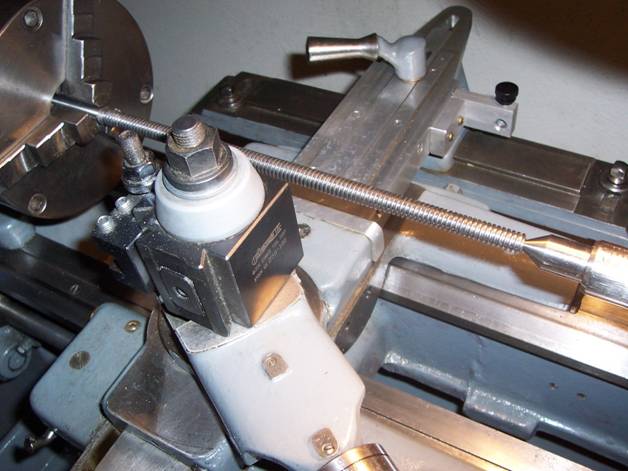
The oldest piece of machinery that I have is a South Bend 10 inch heavy lathe. It has become somewhat of a project piece at times having come without a thread dial indicator and a rear cover for the cross feed assembly. It’s also in need work on the taper attachment since I don’t have room for the collet stand. The pictures below show the lathe with my own special touches.
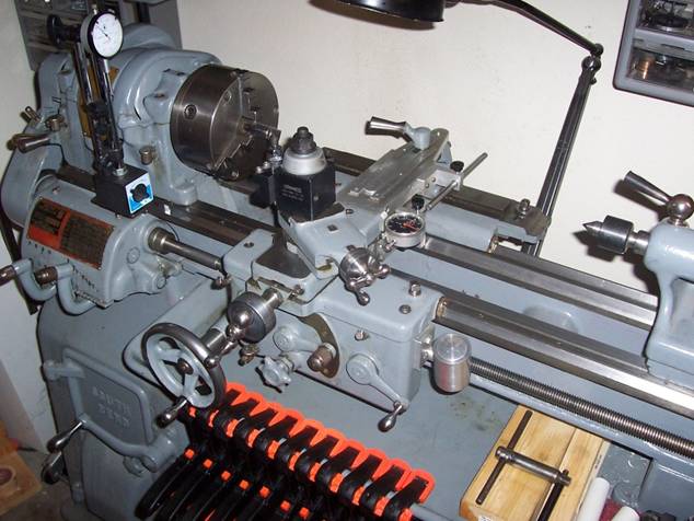
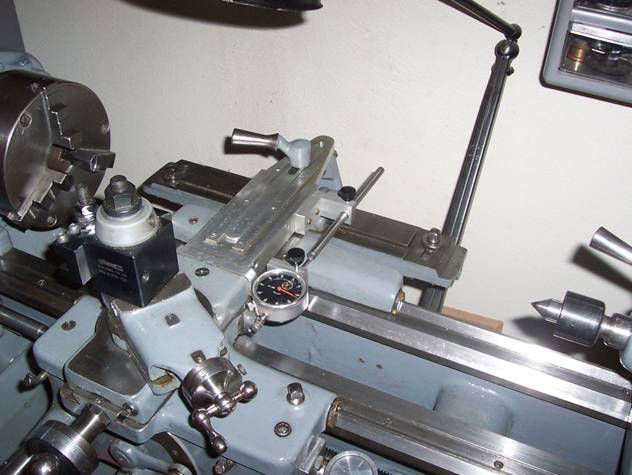
I upgraded the electrical system and installed a standard two phase 220V 3 hp electric motor to drive this lathe which is used for larger gunsmith work since my normal product is the manufacture and development of miniature military items that I turn out on a much smaller jeweler’s lathe.
When I was cutting some threads I noticed that the cross feed had entirely too much backlash – it was measuring 140 thousandths and I was afraid it would soon loose its engagement altogether, so here I go with another project for one of my favorite beasts. A little research on the web showed that there was limited information about what needs to be done. I would like to express my thanks to a shop teacher, Errol Groff at H.H. Ellis Technical High School, for inspiring me to take on this project since I choked after receiving a quote from South Bend for a replacement screw. In all honesty though, South Bend is now providing a much improved ball screw replacement so I believe that has to be the reason for the price quoted. Since I have no aspirations for making this a CNC machine at this time, a ball screw is more than I need and certainly more than I am willing to pay.
Day 1
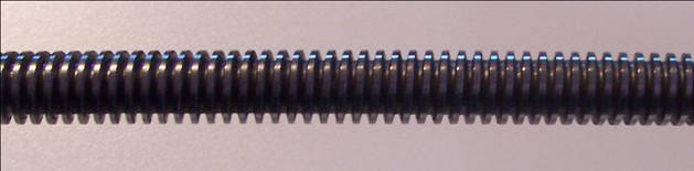
I decided that it would be nice to use this machine to make its own pieces just to see if I could do it without the need to use another lathe. I dismantled the cross feed assembly and removed the cross feed screw, took some rudimentary measurements, and then reassembled the lathe so I could make a new screw and a new nut – both were severely worn as indicated in the Figures 1. The acme threads were pointed in the most heavily traversed area of the lead screw and the brass nut was worn almost as bad. I sketched out the dimensions and have included them in Figure 2 below. I plan to use W-1 drill rod to produce these parts. My desire is to machine the screw as two different pieces, then press them together and silver solder them. This will permit easy replacement of the screw in the future if it wears significantly and I don’t plan on hardening the screw since it may potentially warp. The pieces drawn atop the dimensions in Figure 2 illustrate my planned approach for part design.
The acme threads will be cut in a 7/16 piece of drill rod and the bearing portion of the lead screw will be cut from a piece of ¾ drill rod. I plan to cut the nut from some scrap brass that I picked up at the local scrap yard. I also looked around the shop and decided I will sacrifice a large paddle bit to make a tool to cut the internal threads for the nut keeping in mind that it will have to be very sharp with low rake angles. Given the size and length of the tool I also need to take small cuts to minimize tool flexing. (All this because I don’t have a 7/16-10 LH Acme tap - some of the things I’ll do when I don’t have the right tools even amaze me upon reflection.)
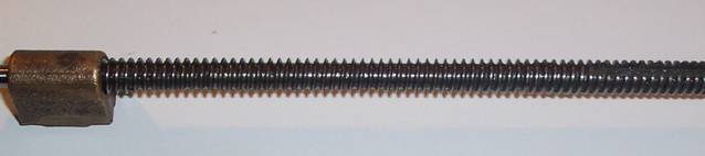 Figure 1. Lead Screw Removed from Lathe Shows Severe Wear with Pointed Threads
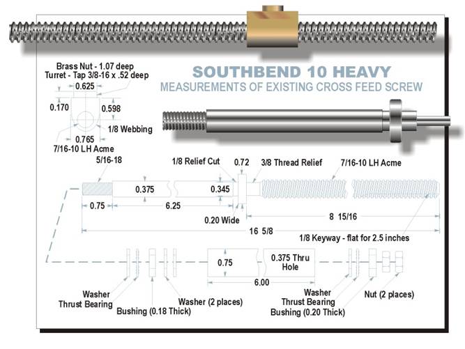
Figure 2. Measurements Taken From Existing Cross Feed Screw and Planned Parts
Day 2
I’ve ordered the drill rod and it should be here in a couple of days. I also started machining the brass nut. Well, you know what they say about the best laid plans of mice and men – I never did get the paddle bit to work like I wanted. Even though it was sharp enough to cut your finger it just had too much flex to smoothly cut the threads in the nut. I looked through my catalogs and didn’t find any nuts already tapped in that thread. As much as I hated, I ended up ordering a tap from www.e-taps.com after calling around and getting quotes from local machine shops to tap it for me. That makes the brass nut relatively expensive but saves me much wasted time so all in all I guess that it’s worth it.
Day 4
Much to my surprise the tap that I ordered just arrived. I found it to be of excellent quality and proceeded to complete the brass nut. The images of the nut are shown below just after I tapped it using a tap guide on the milling machine. As you can see, the piece of brass that I used is quite odd shaped and I had to add a piece so that it would lock in my 4-jaw chuck without the bottom end moving into the jaw slot – remember that I had originally tried to cut the Acme threads on the lathe. I could’ve just drilled a hole had I known that I was going to use a tap. However, adding the piece of aluminum provided a bonus by permitting me to accurately hold the nut in the mill vise. Now I am waiting on the drill rod and as soon as I cut those threads I’ll finish machining the nut – the outside dimensions are not that critical.
One of the things that I don’t have for this lathe is a follower rest so I will turn the threads two or three inches at a time by plunging into the threads. I have done this in the past and it has always worked well for me providing I was careful about lining up the threads after each move in the chuck.
Day 6
The drill rod finally arrived and now for some thread cutting. After making a sharp tool ground for a 29 degree included angle using an acme thread gauge, and then aligning the tool using the same gauge as illustrated in the figure below, I am ready to start cutting.
I finished cutting the threads as planned and they are illustrated in the figures below.
The finished pieces are shown below. I will silver solder them and finish milling the brass nut and then it will be ready to install. The fit between the two pieces is snug enough that they don’t need to be forced but there’s a suction pop when you try and pull them apart. I used a #33 drill to put a pilot hole about an inch and a half deep in the lead screw and then turned the other piece to a diameter that provided a snug fit. I used a die from my local hardware store to cut the 5/16-18 threads on the end of the bearing portion of the lead screw. Next time, I will turn these threads because the die didn’t do as nice a job as I had hoped and made some small gouges in the threads in a couple of places – I don’t think the quality of this die was very good even though it was the best one I could find locally.

Day 7
Well, I finally cut the excess brass off of the nut and rounded the outside. This dimension isn’t critical since there’s lots of room in the channel that it runs in. I also drilled a 1/8 inch through hole into the acme threads where I had ran the 3/8-16 tap since the nut itself forms part of an oil port for the nut itself.
I milled a 1/8 inch keyway into the threads on the end opposite the #33 pilot-hole using a keyway saw. I went 1/8 inch deep as well. I suppose that a 1/8 inch end mill may have done as well. I silver-soldered the two pieces together after cleaning them thoroughly and painting flux onto the pilot rod. It’s now time to dismantle the lathe once again and test this out.
I had to polish the bearing end of the cross feed screw to get it to fit nicely into the taper attachment. I did this with some 320 grit sandpaper in the lathe – had lots of room to work with the cross feed assembly removed. Everything went together very well after polishing the shaft. The fit is excellent and I only have five thousandths of end play. That’s another job done and one less thing to worry about.